- Refrigerant carries heat; the compressor changes its pressure and temperature, while fans move air.
- A reversible design exchanges the coils’ heat-transfer roles for heating and cooling; winter operation depends on the actual system and controls.
- COP, heat capacity and accumulated energy answer different questions. Match their conditions and units.
- Use a clearly assumed energy calculation to ask better questions, then request building-specific selection and commissioning evidence.
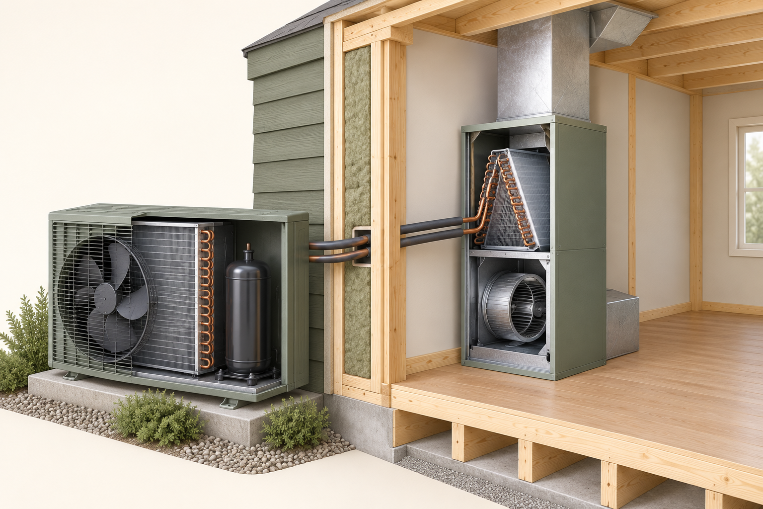
The cutaway puts an outdoor fan and coil beside a separate indoor coil and blower. Illustrated tubes cross the wall between the equipment; there is no air duct joining the outdoor fan to the room.
About this illustration
This is a conceptual equipment pair. It does not identify your models, the tubes’ actual roles, accepted pairing, complete piping, control sequence, capacity or commissioning results. This is a conceptual teaching model, not an assessment of your home.
4 picture lessons appear beside the questions in this guide. Use them to understand the explanation, then consider what it means for your home.
How does a heat pump carry outdoor heat into the home?
A heat pump warms a home by collecting heat somewhere else and delivering it indoors. In an air-source system, that starting place is outdoor air. Electricity runs the machinery that makes the transfer possible.
Refrigerant is the working fluid circulating inside the system. A heat exchanger, often called a coil, lets heat pass between that fluid and the air beside it. Air passes over the exchanger, while refrigerant travels inside its passages.
The outdoor fan moves air past the exchanger; it does not send outdoor air through the refrigerant tubes into your rooms. The following four jobs explain a conceptual heating cycle rather than installation positions or service instructions.
First, the outdoor exchanger absorbs heat. Refrigerant entering it is colder than the outdoor air under the operating conditions. Heat can therefore move from the air into the refrigerant, even when that air feels cold to you. As it absorbs heat, the refrigerant boils and becomes vapour. In this role, the exchanger is the evaporator.
Second, the compressor squeezes the refrigerant vapour, raising its pressure and temperature. This takes electrical work. The compressor acts on the refrigerant; the outdoor fan and indoor blower have different jobs moving air.
Third, the warmer refrigerant releases heat at the indoor exchanger. Air passing over that exchanger receives heat for the home. The refrigerant cools and condenses into liquid, giving this exchanger its condenser role.
Ducts may distribute the warmed air, or a ductless indoor unit may serve its intended room area. The installed design determines the actual distribution. A closed cabinet or a fan noise alone cannot tell you how much useful heat reaches the rooms.
Fourth, an expansion device lowers the refrigerant pressure before it returns to the outdoor exchanger. The resulting cooler liquid-and-vapour mixture can absorb heat again. The refrigerant recirculates; it is not a fuel consumed on each circuit.
Keep questions about refrigerant condition, charge or leaks with an appropriately qualified equipment professional, without opening covers or altering refrigerant components.
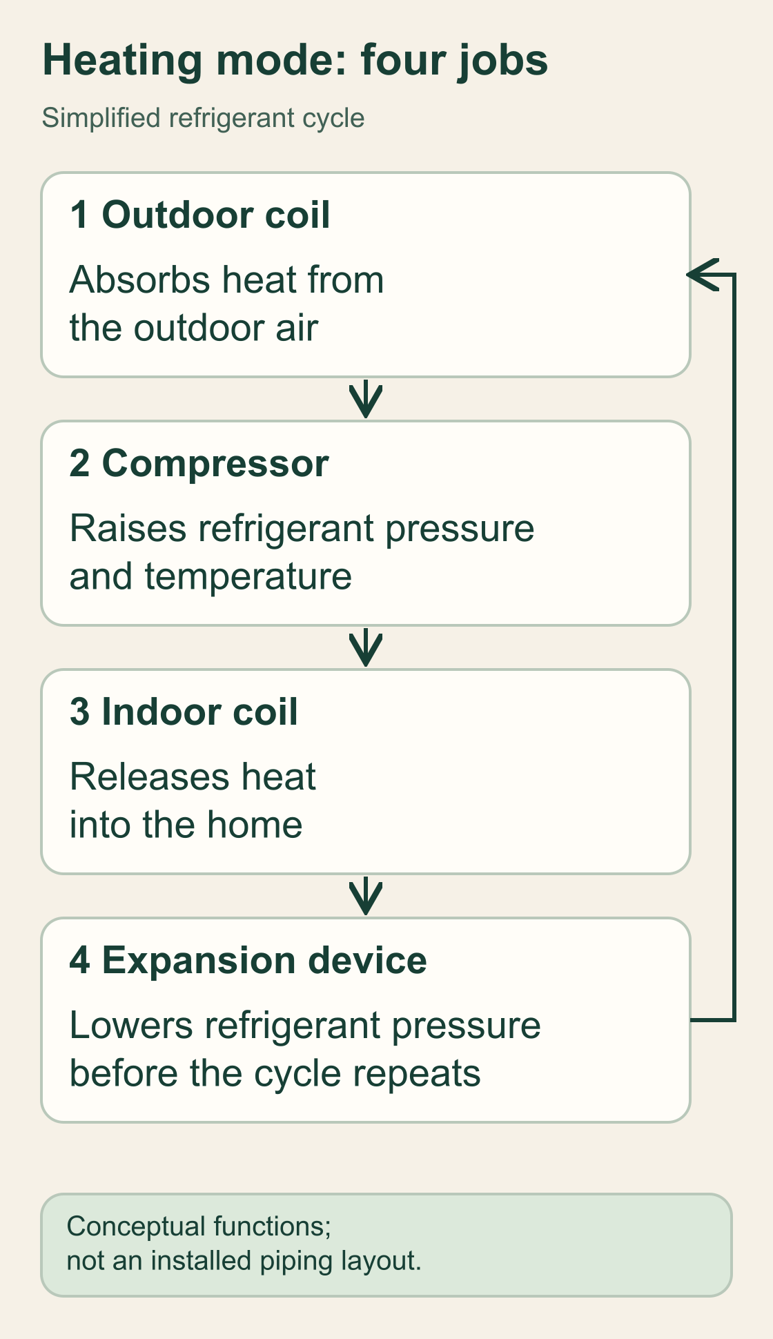
Four jobs carry heat through the heating cycle
The outdoor coil takes in heat, the compressor raises refrigerant pressure and temperature, the indoor coil releases heat, and the expansion device lowers pressure before the cycle repeats.
Numbers identify the parts explained below.
- Outdoor coil
In heating mode, refrigerant takes in heat from outdoor air at this exchanger.
- Compressor
Electrical work raises the refrigerant vapour’s pressure and temperature.
- Indoor coil
Refrigerant releases heat at the indoor exchanger so the home can receive it.
- Expansion device
Pressure falls before the refrigerant returns to the outdoor exchanger and the cycle repeats.
What does this illustration leave out?
The arrows explain the order of functions. They do not map installed pipes, identify a product or show pressures, temperatures or measured performance. Read the complete labelled explanation below.
Which installed components collect, move and release heat, and how is heat delivered to the rooms?
Explore this with HomeAI ↗Opens an editable question. Nothing is sent until you choose to send it.Read the complete picture lesson
Four jobs carry heat through the heating cycle
Read these four jobs in order for a conceptual air-source heating cycle. The refrigerant circulates; the outdoor and indoor air stay beside their own heat exchangers.
- Outdoor coil / evaporator
- The colder refrigerant absorbs heat from outdoor air. As it absorbs heat it boils into vapour.
- Compressor
- Electrical work raises the vapour’s pressure and temperature. This is different from a fan moving air.
- Indoor coil / condenser
- Warmer refrigerant gives heat to the indoor side and condenses into liquid. The installed distribution carries useful heat towards the rooms.
- Expansion device
- The pressure falls before the refrigerant returns to the outdoor exchanger to absorb heat again.
In cooling mode, the exchanger roles reverse: heat is collected indoors and released outdoors. The two exchangers do not have to swap physical positions. This diagram teaches the heating functions, with simplified order rather than an installed piping layout.
What remains unknown: No actual refrigerant condition, component identity, temperature, pressure, model selection or measured performance is established.
Useful next question: Which installed components collect, move and release heat, and how is heat delivered to the rooms?
Three jobs behind the warmth you feel
- Refrigerant cycleAbsorbs, carries and releases heat. The compressor changes refrigerant pressure and temperature; fans do not perform this job.
- Air distributionMoves air over the exchangers and, where designed, through ducts or a room unit. Ask how the intended rooms receive delivered heat.
- Controls and supplementary equipmentRequest and coordinate operation under the installed plan. A wall display or cabinet does not establish the actual control sequence.
Why can it deliver more heat than the electricity it uses?
The delivered heat includes energy moved from the outdoor environment as well as electrical energy supplied to the machinery. Electrical work makes the transfer possible. Counting only the electricity entering the system would leave out the outdoor heat it collected.
Fictional energy example: during one invented interval, assume 3 kilowatt-hours (kWh) of electricity enter the chosen heat-pump system boundary and 6 kWh of heat enter from outdoor air. Assume 9 kWh of useful heat leave that boundary for the home, with no separately modelled losses or change in stored energy. These are invented teaching quantities, not equipment measurements.
For this example, the useful heat divided by electrical energy is 9 ÷ 3 = 3. This is the assumed coefficient of performance, or COP, for that same interval and boundary. The 6 kWh of outdoor heat explains the additional delivered energy.
The invented example does not describe an actual product rating or guarantee that every operating interval has COP 3.
NRCan explains that performance changes with source and receiving-side conditions. Published product figures use specified conditions, while seasonal measures combine performance under a defined framework. Keep those conditions with the number. One appealing COP value cannot tell you how much heat the home needs, how the rooms receive it or what a full winter will cost.
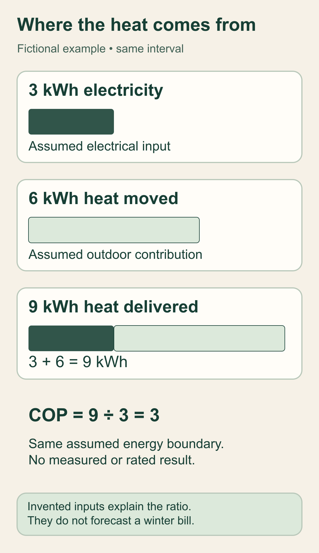
Electricity and moved heat both enter the example
The invented bars use the same scale and interval: 3 kWh of electricity plus 6 kWh of outdoor heat gives 9 kWh delivered, with no separately modelled losses or stored-energy change.
Numbers identify the parts explained below.
- 3 kWh electricity
This invented energy input runs the machinery during the chosen interval. It is energy, not an equipment capacity.
- 6 kWh moved heat
This is the invented heat collected from outdoors across the same boundary and interval.
- 9 kWh delivered heat
The assumed useful output is the two inputs combined: 3 + 6 = 9 kWh.
- Assumed COP of 3
Useful heat divided by electrical input is 9 ÷ 3 = 3 for this fictional interval.
What does this illustration leave out?
These assumed quantities are not a product rating, field measurement, household energy total or seasonal forecast. Every quantity uses the same chosen heat-pump system boundary. Read the complete labelled explanation below.
Do the compared figures use matching units, conditions, intervals and system boundaries?
Explore this with HomeAI ↗Opens an editable question. Nothing is sent until you choose to send it.Read the complete picture lesson
Electricity and moved heat both enter the example
These quantities are explicitly invented. Across one chosen heat-pump system boundary and the same invented interval, assume 3 kWh of electrical input, 6 kWh of outdoor heat collected and 9 kWh of useful heat delivered.
- Electrical input: 3 kWh
- The dark bar represents assumed electrical energy used during that interval. It is not a 3 kW product capacity.
- Outdoor contribution: 6 kWh
- The lighter bar represents assumed heat moved from the outdoor environment over the same boundary and interval.
- Useful heat delivered: 9 kWh
- The combined bar uses the same graphical scale: 3 kWh + 6 kWh = 9 kWh.
- Assumed COP: 3
- For those matching energy quantities, COP = 9 kWh ÷ 3 kWh = 3.
The illustration assumes no separately modelled losses and no change in stored energy across the chosen boundary. It is a steady bookkeeping example, not a prediction of how a real unit operates throughout winter. The energy bars have matching units and scale; they contain no equipment test data.
What remains unknown: The example does not provide a rated COP, household total, installed capacity, measured efficiency, utility charge, savings result or seasonal operating forecast.
Useful next question: Do the compared figures use matching units, conditions, intervals and system boundaries?
What changes in cooling, frost removal and colder weather?
For a reversible design in cooling mode, the home is the place heat is collected. The indoor exchanger absorbs heat from indoor air, and the outdoor exchanger releases it outside. A reversing arrangement changes those exchanger roles. The compressor still does work on refrigerant.
The picture teaches heat-transfer jobs; the actual equipment drawing explains the model’s tubing, valves and operating arrangement.
During air-source heating, the outdoor exchanger can be cold enough for moisture in the passing air to freeze on it. A defrost sequence deals with that accumulated frost. NRCan describes common reverse-cycle defrost, which temporarily sends heat to the outdoor exchanger.
How indoor delivery and supplementary equipment behave during that event depends on the system and its controls.
A brief observed change and a persistent loss of comfort deserve different service questions. Record when it happened, outdoor conditions, displayed messages and which rooms changed, from ordinary safe access. That record helps describe the event. It cannot establish normal defrost, a refrigerant fault or a failed part. The winter defrost guide develops this particular observation task.
Colder outdoor conditions can change available heating capacity and efficiency. The home’s heating requirement also changes with its conditions. A designed supplementary system may contribute when needed under the intended controls. Ask for the actual selection basis and sequence instead of adopting one outdoor-temperature cut-off for every Canadian climate, product or installation.
A ground-source heat pump obtains heat through a ground or water arrangement rather than this outdoor-air coil arrangement. Some heat pumps deliver heat to water instead of room air. The broad transfer principle connects these systems, but their source routes, distribution and winter questions differ.
An air-source illustration cannot establish the suitability of a ground loop or water system.
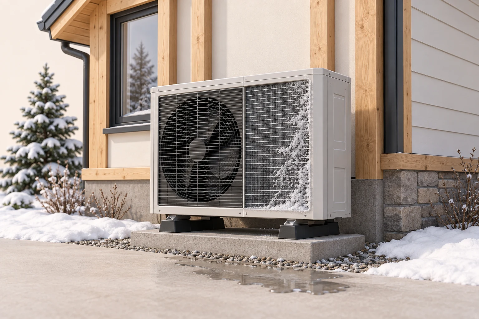
Frost, frost removal and room comfort have different questions
The pictured fins have frost on them and water lies below the outdoor unit. These features introduce the separate questions of coil condition, frost-removal operation and where water goes.
Numbers identify the parts explained below.
- Finned outdoor surface
In heating mode, an outdoor exchanger can become cold enough for moisture to frost on it. Applicable controls remove frost so heat exchange can continue.
- Outdoor cabinet
Record a change noticed during ordinary use with its time and model. Do not open covers or deliberately provoke a defrost event.
- Water and the room
Water handling and indoor comfort are separate observations. The picture supplies no approved drainage arrangement or measured room output.
What does this illustration leave out?
The picture does not identify an actual operating mode, event sequence or fault. Frost and a puddle need model instructions, weather context and qualified findings to interpret. This is a teaching cutaway. Keep equipment covers and building finishes in place.
What does this model’s documented frost-removal sequence explain, and what needs a separate service assessment?
Explore this with HomeAI ↗Opens an editable question. Nothing is sent until you choose to send it.What does the energy calculator actually calculate?
The calculator starts with an assumed amount of heat delivered to the home in kWh. It divides that amount by the entered COP to estimate electrical energy, then multiplies by the entered electricity price.
Its resistance-heating comparison assumes electricity equal to the entered delivered heat. This is arithmetic for a stated scenario, with the same heat requirement in both columns.
For example, enter an invented 900 kWh of delivered heat and a fixed assumed COP of 3. The calculated electricity is 300 kWh. At an invented energy price of CAD 0.20 per kWh, the calculated energy charge is CAD 60. The figures describe those inputs only; no Canadian tariff, household bill or available equipment performance is represented.
A lower assumed COP increases calculated electricity for the same delivered heat. Changing the entered heat requirement changes the answer too. This makes the calculator useful for understanding which assumption drives a comparison.
The entered COP remains an assumption: moving a slider does not supply product data, a measured operating ratio or a seasonal model for your address.
The tool does not model hourly weather, defrost, supplementary heat, cycling or changing household use. Its price calculation leaves out fixed charges, taxes, financing, other fuels and other applicable account charges.
Ask an appropriate professional to explain a building-specific proposal and the actual local account arrangement before using an energy scenario for a purchase or replacement decision.
Why can an efficient unit still leave a room cold?
Efficiency answers how useful output relates to energy input. Capacity answers how quickly useful heat can be supplied under stated conditions. A home can need heat faster than a selected system can deliver it at a particular condition, even if an efficiency figure looks attractive.
The required delivery rate is the heating load; it depends on the building and the design conditions.
Distribution adds another question: does the delivered heat reach the intended spaces? A ducted system needs an assessed air-distribution arrangement; a ductless head serves the area considered in its design. Visible room units do not establish whole-home coverage. Ask the provider how the plan accounts for the rooms, doors, layout and intended use of this particular home.
One cold room may involve distribution, that room’s heat loss or control behaviour. Several cold rooms can raise wider output or operating questions. These patterns organise the assessment without identifying a cause. Keep observations of room differences, timing and ordinary use together.
Do not alter fan wiring, refrigerant settings or ducts to make the pattern resemble a guessed diagnosis.
A high electricity bill is another kind of observation. The billing period, weather, household use, electricity price and other loads can all affect it. Compare quantities and dates before comparing charges.
A qualified service assessment can investigate equipment operation; a building energy assessment addresses a different scope. Either report should state what was measured, modelled and left unassessed.
What should a contractor explain before I choose a system?
Start with the intended job: which spaces need heating and cooling, under which local conditions, and through what distribution? Ask how the home’s assessed heating and cooling loads informed selection. Request the exact indoor and outdoor models and the performance information used for those conditions. A cabinet photograph or one nameplate figure cannot replace that explanation.
Ask for the intended supplementary equipment and control sequence, where relevant. Request the basis for distribution, electrical work and any necessary permissions from the appropriate providers and authorities. Canadian climate, building form, utility arrangements and local requirements vary. HomeAI teaches the questions; it does not select a unit size, approve an installation or establish local compliance.
Ask what commissioning will check after installation and what record you will receive. Commissioning is the agreed verification of the installed arrangement. Keep the stated checks, relevant readings, settings documented by the provider and exclusions with the equipment file. A completed installation invoice establishes its described work, without automatically answering every room-comfort or future-energy question.
An EnerGuide evaluation can add building context. NRCan distinguishes its home rating, Homeowner Information Sheet and Renovation Upgrade Report. The rating uses standard operating conditions to compare homes, while reported estimates can also address household conditions.
Read the complete documents and recommendations with the advisor. They do not measure refrigerant condition or guarantee matching utility bills.
For a purchase, a realtor can coordinate authorized requests and specialist access. Ask about the provider’s actual qualifications, scope and availability. If someone is described as HAUSE-trained, ask what training they completed and how it relates to the question. Coordination and training cannot replace the equipment professional’s findings or the energy advisor’s explanation of the home.
Indoor and outdoor air stay on their own sides
The cutaway puts an outdoor fan and coil beside a separate indoor coil and blower. Illustrated tubes cross the wall between the equipment; there is no air duct joining the outdoor fan to the room.
Numbers identify the parts explained below.
- Outdoor fan and coil
The outdoor fan moves outdoor air across the exchanger. In heating mode, the refrigerant absorbs heat there; the fan does not send that outdoor air through refrigerant tubes into the rooms.
- Indoor coil and blower
The indoor exchanger passes heat to indoor air in heating mode. The blower and connected distribution arrangement move that air towards the rooms.
- Two air-side jobs
Air passes beside an exchanger while refrigerant circulates inside the system. Ask how the actual unit and distribution serve the home.
What does this illustration leave out?
This is a conceptual equipment pair. It does not identify your models, the tubes’ actual roles, accepted pairing, complete piping, control sequence, capacity or commissioning results. This is a teaching cutaway. Keep equipment covers and building finishes in place.
How do the selected equipment, distribution and controls serve the rooms, and what installation and commissioning evidence supports that explanation?
Explore this with HomeAI ↗Opens an editable question. Nothing is sent until you choose to send it.How are kilowatts, kilowatt-hours and COP different?
A kilowatt (kW) describes a rate. Heat-output capacity in kW tells you how quickly heat can be delivered at the stated conditions. Electrical input in kW tells you how quickly electricity is being used at its identified boundary. Both use the same power unit, but one describes useful heat and the other describes electrical input.
A kilowatt-hour (kWh) describes an accumulated amount of energy. In a separate fictional steady-rate example, delivering 9 kW of heat for exactly one hour delivers 9 kWh. Using 3 kW of electricity steadily for that hour uses 3 kWh.
Real output and input can vary over an hour; multiplication by time needs an appropriate steady rate or integration of the varying rate.
COP has no unit because it divides corresponding useful heat by electrical input. The fictional rate ratio is 9 kW ÷ 3 kW = 3; the matching one-hour energy ratio is 9 kWh ÷ 3 kWh = 3.
Keep the operating condition, interval and boundary consistent. Rated output from one condition and an unrelated household input reading cannot establish installed COP.
A seasonal metric combines specified conditions according to its method. An annual energy estimate answers an accumulated-use question. A nameplate or sales sheet may contain several of these numbers together. Ask the contractor to name each quantity, its unit and applicable conditions before comparing proposals. This prevents efficiency, capacity and annual energy from becoming one vague “performance” claim.
Give every performance number its own question
- Heat capacity · kW of heatHow quickly can useful heat be delivered at the stated conditions? Compare against the assessed heating load and distribution plan.
- Electrical input · kW of electricityHow quickly is electricity being used at the identified boundary? It differs from heat-output capacity.
- Energy · kWhHow much heat or electricity accumulated during the named interval? Keep the quantity, boundary and dates identified.
- COP · no unitWhat is corresponding useful heat divided by electrical input? Match the condition and boundary; an assumed ratio is not a measured result.
- Seasonal performance · named methodHow does the published method combine specified conditions? Retain its assumptions rather than treating it as the household’s future bill.
How would a fictional owner compare two proposals?
Fictional example: Sam receives two heat-pump proposals for the same home. One highlights a seasonal product figure. The other explains the assessed load, intended room coverage and supplementary plan. Sam asks both contractors for comparable selection information before treating either offer as the better choice. No actual product, defect or professional finding is represented here.
To understand the arithmetic, Sam invents the same 900 kWh of delivered heat for both scenarios. Fixed assumed COP 3 gives 300 kWh of electricity; fixed assumed COP 2 gives 450 kWh. The invented difference is 150 kWh. This isolates the entered COP assumption, with no hourly weather, supplementary heat, defrost or household model added.
That arithmetic cannot determine which proposal would keep the rooms comfortable. Sam asks each provider how capacity at relevant conditions, distribution and controls fit the home. Sam also asks what any energy estimate includes, which prices and use assumptions it adopts, and what commissioning will verify. Missing answers remain named questions rather than an assumed failure.
After installation in the fictional story, Sam records a recurring room-temperature difference and takes it to the responsible provider. The provider is asked to define an assessment of operation and distribution, with complementary building questions where needed.
Sam keeps the report, its exclusions and follow-up together. A successful check of one component cannot establish every room’s performance or the next winter’s bill.
Keep learning about the connected parts
Heat-pump energy lab
Compare electricity needed to deliver the same heat.
Electricity = heat delivered ÷ COP
Illustrative energy-only comparison. Excludes fixed charges, defrost, backup heat and hourly weather.
Practice the distinction.
Sam separates the proposal from the energy arithmetic
Fictional example: two heat-pump proposals provide different levels of explanation, while Sam uses invented energy inputs to understand the calculation.
Reported observations
- Both scenarios assume 900 kWh of delivered heat.
- Fixed assumed COP 3 gives 300 kWh of electricity; fixed assumed COP 2 gives 450 kWh.
- The proposal comparison still needs load, room distribution, relevant product conditions and control information.
Compare the explanations
Expand each possibility to see the evidence needed to distinguish it. Similar symptoms can have different mechanisms.
The arithmetic answers an assumed energy question
The 150 kWh difference follows from the invented COP inputs at equal delivered heat.
The stated quantities, consistent boundary and calculation; no actual equipment conclusion.
The installed choice needs a different evidence set
Comfort and suitability depend on assessed load, capacity, distribution and intended operation.
The qualified provider’s building-specific selection rationale, commissioning scope and relevant findings.
A useful next question
Sam requests comparable technical explanations and keeps estimated, rated, measured and missing information identified.
No product selection, equipment fault, saving, actual tariff or future household result is established.
Know what the words mean.
- Refrigerant
- The working fluid that absorbs, carries and releases heat while circulating inside the heat-pump system.
- Heat exchanger or coil
- A surface arrangement that transfers heat between refrigerant and air or another medium, which follow separate routes.
- Evaporator
- The exchanger’s heat-absorbing role: refrigerant receives heat and boils into vapour.
- Compressor
- The machine that compresses refrigerant vapour and raises its pressure and temperature using electrical work.
- Condenser
- The exchanger’s heat-releasing role: refrigerant transfers heat away and condenses into liquid.
- Expansion device
- The component that lowers refrigerant pressure before the cooler mixture returns to absorb heat.
- Capacity
- A rate of useful heat delivery or removal at stated conditions, commonly expressed in kW of heat.
- COP
- Corresponding useful heat output divided by electrical input at a consistent stated condition, interval and boundary. The ratio has no unit.
- Kilowatt-hour (kWh)
- An amount of energy, distinct from a kilowatt (kW), which describes an energy rate.
- Seasonal metric
- A performance measure combining specified conditions under a named seasonal method; it is not a future household bill.
Questions to bring
to the conversation.
- What are the exact indoor and outdoor models, and which spaces is the installed design intended to serve?
- How do assessed loads, local conditions, distribution and any supplementary controls support the selection?
- Which numbers are heat capacity, electrical input, energy, COP or a seasonal metric, and under what conditions?
- What do the commissioning and service records establish, and which rooms or questions were outside their scope?
- What assumptions explain an energy estimate, and how do they differ from actual household use and bills?
Separate a showing observation, an existing record and a new professional assessment. Unknown means a question remains; it does not automatically mean a defect.
Use the evidence planner ↗Go to the source.
Original HomeAI explanation informed by these public references. Sources support the underlying guidance; they have not reviewed or endorsed HomeAI. Diagrams are conceptual, and calculator outputs depend on your inputs.
NRCan’s Canadian heat-pump, house-operation and EnerGuide pages were read in full on October 5, 2026 (America/Edmonton). Their visible modification dates are December 24, 2025; September 29, 2025; and November 28, 2025. They support the mechanisms and report distinctions taught here. Linked documents, product manuals and source figure pixels were not read. No universal temperature cut-off, service interval, product rating, current programme or local installation rule is imported. All numerical examples are invented; source-object dates remain unchanged.
Publication & source review
First published .
Sources reviewed .
Have a question about your home?
Start with the symptom, timing and what you have observed.
Ask HomeAI