Jump to a question in this guide
- What does an air compressor do that an ordinary fan does not?
- How do the motor, pump, receiver and outlet connect?
- How does a piston actually compress air?
- Why does the receiver keep pressure when the motor is quiet?
- How do the pressure switch, regulator and safety valve differ?
- Why are there two gauges, and what does each leave out?
- How should air delivery and tool demand be compared?
- Why does water collect in a machine that takes in air?
- What do oil-free, filtration and dry-air claims really mean?
- How do hoses, couplers and accessories become part of the system?
- What matters about the compressor's location and electrical supply?
- Which observations are useful without an owner pressure test?
- Why might a tool slow down while the compressor runs?
- What should a service report and equipment handover contain?
- Work through a fictional compressor and air-sander mismatch
- How do Canadian and product limits change the answer?
- The piston pump delivers air; the receiver stores compressed-air energy after the motor can stop.
- Pressure switch, regulator and safety valve perform separate control and protection jobs.
- Tank pressure, outlet pressure, air delivery and tank volume are different quantities.
- A tool working briefly does not establish a sustainable match; never direct compressed air at people or use it as breathing air.
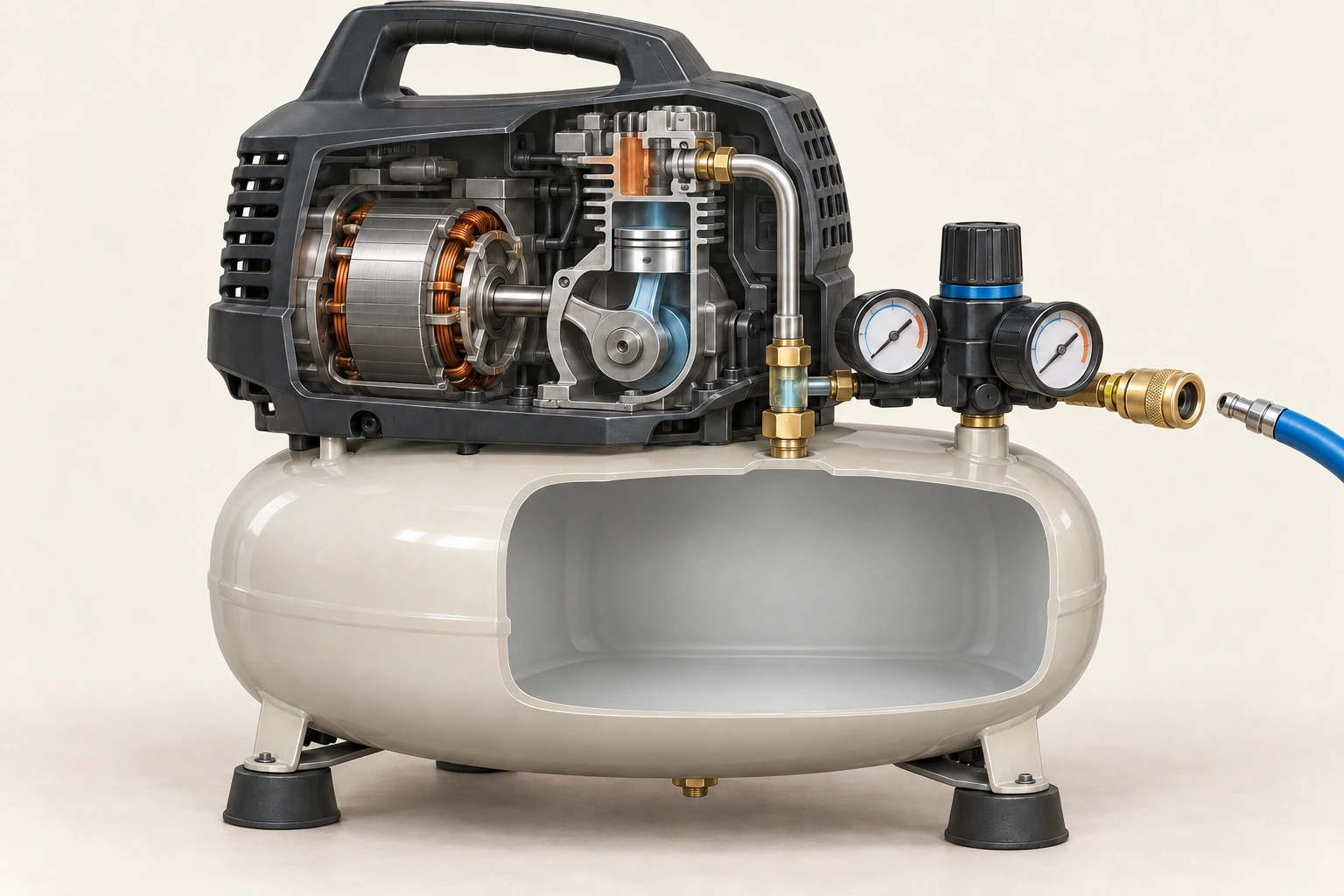
The motor/pump assembly supplies compressed air to the receiver. The separate manifold, gauges and outlet concern stored pressure and delivery to the work route.
About this illustration
Conceptual motor, piston and discharge-tube relationships; individual fitting roles and full tank-inlet passage are simplified. No measured pressure, tank condition or exact Bostitch internals. This is a conceptual teaching model, not an assessment of your home.
9 picture lessons appear beside the questions in this guide. Use them to understand the explanation, then consider what it means for your home.
What does an air compressor do that an ordinary fan does not?
An air compressor takes in surrounding air and compresses it so that it can supply an intended air-powered task. A receiver tank stores compressed air between the pump and the outlet. That stored air is useful energy, but it is also a hazard. A stopped motor does not establish an empty tank, and an unplugged machine can still contain pressure in the receiver, hose or connected equipment.
Never direct compressed air at a person or use it to clean skin or clothing. CCOHS explains the hazards of the jet, flying material, airborne dust and injury. Air from a general-purpose compressor is not breathing air. Do not use it for breathing equipment, food applications or a different task merely because the hose or fitting can be adapted. The actual equipment and intended application require their own suitable arrangements.
The distinct subject here is a small household reciprocating compressor: a piston pump, receiver, pressure controls and outlet supply. The pressure-washer guide concerns a liquid-water route and nozzle; an air compressor stores compressible gas and can supply different accessories. A shop vacuum moves an air stream to carry debris through collection equipment. These machines have different functions even if each contains a motor and makes a familiar sound.
The named controls example is Bostitch BTFP02012, using its September2019 manual, complete English body, and a separate Quincy piston explanation. Canadian CCOHS provides hazard education, not approval of a household workshop or tool. Other products have different pumps, lubrication, cooling, duty limits and controls. Learn the relationships, then use the exact model's instructions and appropriate service advice rather than this guide as an operating or repair sequence.
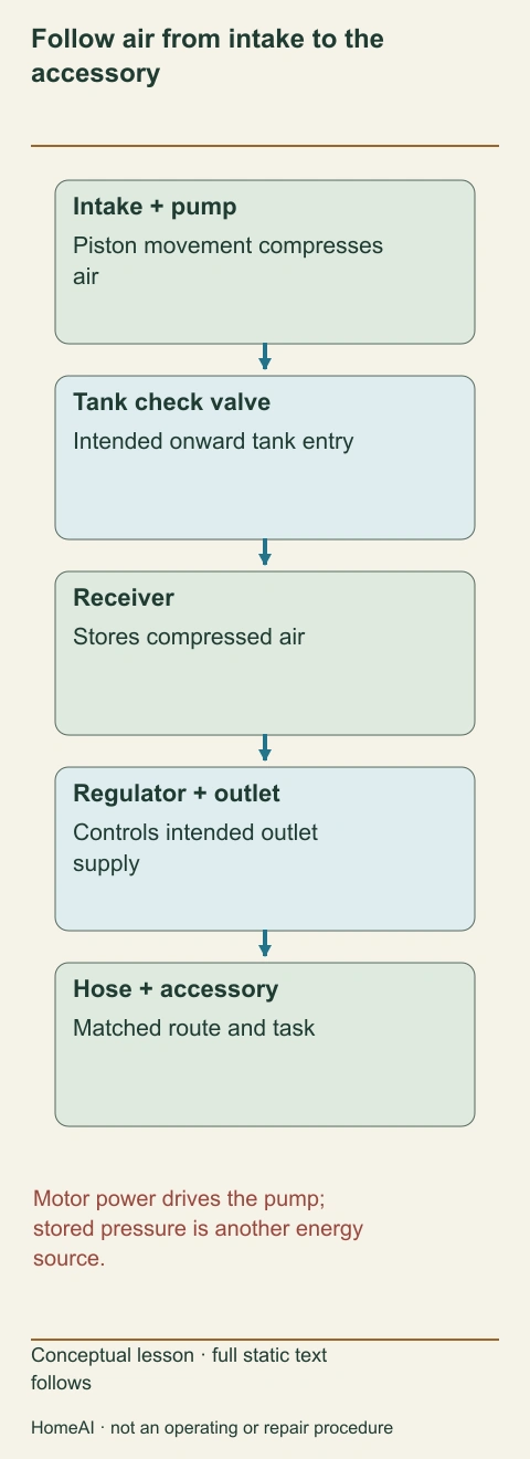
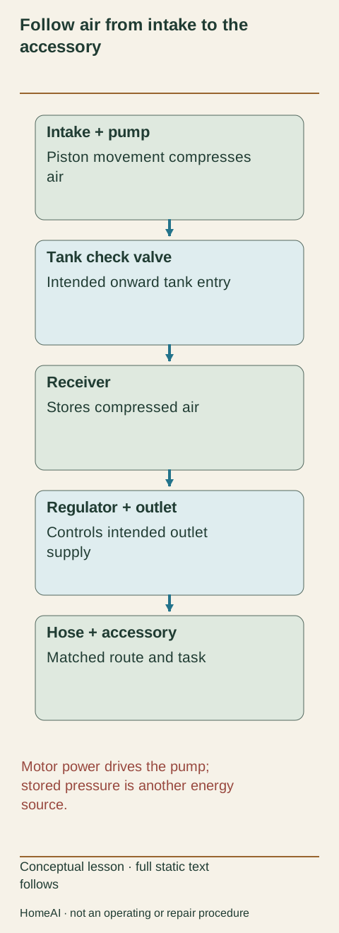
Follow air from intake to the accessory
The motor drives the pump; air travels through the intended tank inlet to the receiver, then through the regulated outlet to a matched accessory. Stored air remains a separate energy source after the motor can stop.
Numbers identify the parts explained below.
- Motor and pump
Rotation drives repeated air compression.
- Tank check valve
Permits tank entry and helps retain stored pressure.
- Receiver
Stores compressed air.
- Regulator and hose
Supply the accessory under the intended requirements.
What does this illustration leave out?
Conceptual route, not a connection or pressure-release procedure; actual internal passages differ. This illustration explains an idea. It is not an installation guide.
Which part of the complete compressor-to-accessory route was assessed?
Explore this with HomeAI ↗Opens an editable question. Nothing is sent until you choose to send it.Follow air from intake to the accessory
The motor drives the pump; air travels through the intended tank inlet to the receiver, then through the regulated outlet to a matched accessory. Stored air remains a separate energy source after the motor can stop.
- Motor and pump
- Rotation drives repeated air compression.
- Tank check valve
- Permits tank entry and helps retain stored pressure.
- Receiver
- Stores compressed air.
- Regulator and hose
- Supply the accessory under the intended requirements.
Figure scope: Conceptual route, not a connection or pressure-release procedure; actual internal passages differ.
A useful question: Which part of the complete compressor-to-accessory route was assessed?
Full wording shown in this figure
- Follow air from intake to the
- accessory
- Intake + pump
- Piston movement compresses
- air
- Tank check valve
- Intended onward tank entry
- Receiver
- Stores compressed air
- Regulator + outlet
- Controls intended outlet
- supply
- Hose + accessory
- Matched route and task
- Motor power drives the pump;
- stored pressure is another energy
- source.
- Conceptual lesson · full static text
- follows
- HomeAI · not an operating or repair procedure
How do the motor, pump, receiver and outlet connect?
The electric motor supplies rotation to the pump. The pump compresses air and delivers it through the intended discharge route into the receiver. The receiver stores that air, and an outlet route supplies a hose or accessory. A regulator can control outlet pressure, while a pressure switch responds to receiver pressure to control motor operation. These are separate jobs, not several names for one pressure knob.
In the named Bostitch example, a check valve allows air into the tank during pumping and helps retain tank pressure after the pump stops. The manifold includes separate tank and outlet pressure indications. The quick-connect outlet is an interface for the appropriate hose connection, not a promise that every tool with a physically fitting plug is suitable for the compressor or the intended household task.
The whole-unit picture introduces those parts, while the native route diagram makes the intended order explicit. Real tubes and internal passages can be partly concealed by a shroud. A conceptual view is not a plumbing drawing or a parts-identification guarantee. Keep the actual illustrated manual with the machine; never remove the protective shroud or disconnect a pressurized fitting to confirm an educational image.
Understanding the route helps frame a changed-performance question. An accessory that slows may be affected by outlet conditions, the air route, available delivery or its own condition. A tank gauge alone does not measure everything along that route. The service provider needs the actual compressor, hose, accessory and reported work pattern to distinguish a supply mismatch from a restricted route, leak or equipment fault.
The pump supplies a separate receiver
The motor/pump assembly supplies compressed air to the receiver. The separate manifold, gauges and outlet concern stored pressure and delivery to the work route.
Numbers identify the parts explained below.
- Motor
Supplies the pump’s motion.
- Pump
Compresses air for delivery.
- Receiver
Stores compressed air.
- Outlet manifold
Connects indication, regulation and the intended hose route.
What does this illustration leave out?
Conceptual motor, piston and discharge-tube relationships; individual fitting roles and full tank-inlet passage are simplified. No measured pressure, tank condition or exact Bostitch internals. This illustration explains an idea. It is not an installation guide.
Which actual component controls stored pressure and which controls the outlet?
Explore this with HomeAI ↗Opens an editable question. Nothing is sent until you choose to send it.How does a piston actually compress air?
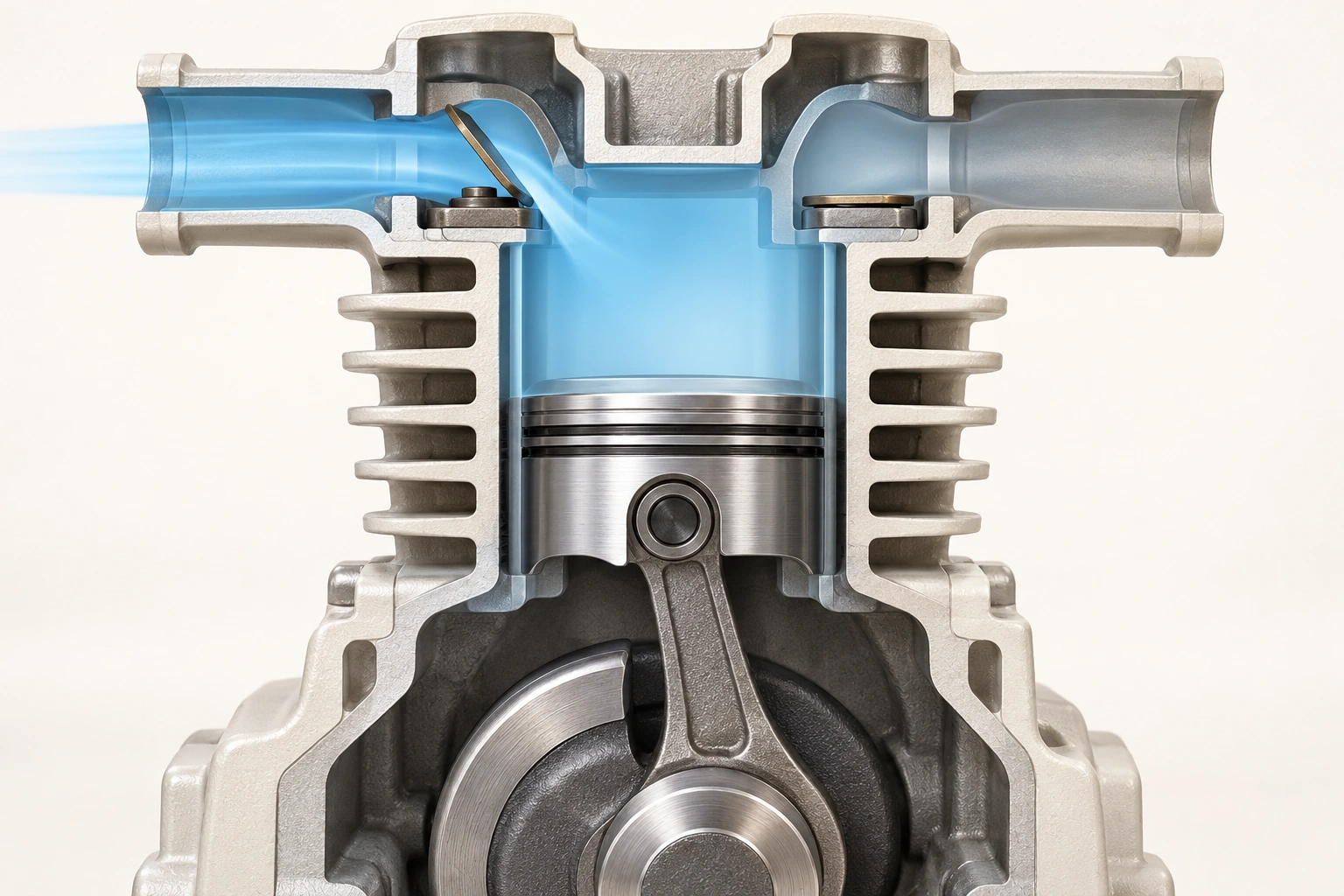
A reciprocating pump uses a piston that moves back and forth in a cylinder. The motor drives a crank, and the connecting rod translates its rotation into piston movement. During intake, an increasing chamber volume lowers pressure sufficiently for air to enter through the inlet valve. As the piston moves back, the inlet closes and the chamber volume decreases, compressing the captured air.
When chamber pressure is sufficient for delivery, the discharge valve opens and air moves onward. Repeating the cycle delivers air into the system or receiver. Quincy's manufacturer explanation supplies this general sequence. The generated close-up shows an intake geometry only; the explanation follows the later compression and delivery stages. The native route follows the air onward through the system. Neither illustration assigns an actual valve design, clearance, temperature or pressure to a household product.
The valves give direction to the changing volume. Without the intended valve behaviour, a moving piston does not necessarily deliver the expected air onward. This explains why a running motor and a noisy pump are not complete performance results. It does not identify a faulty valve in a real machine or give an owner a reason to inspect the cylinder head.
Keep guards and covers in place. The named manual warns about automatic cycling, moving parts, hot surfaces and stored air. Do not open the pump, listen closely at a pressurized joint, or perform a blocked-outlet trial to test the mechanism. A technician can assess the relevant parts under an appropriate service scope; an owner can supply the reported symptoms and equipment identity without creating another hazardous event.
An intake state is one part of a cycle
A larger chamber and separate inlet/discharge valve positions introduce intake; the complete compression lesson explains the following delivery stage.
Numbers identify the parts explained below.
- Chamber
Changes volume as the piston moves.
- Inlet valve
The intended incoming route.
- Discharge valve
A different onward delivery route.
- Crank and rod
Drive repeated piston motion.
What does this illustration leave out?
Single conceptual intake state; the lower crank is partly cropped. No complete cycle, exact named valve construction, opening or pressure experiment. This illustration explains an idea. It is not an installation guide.
How does the actual assessment distinguish pump motion from delivered air?
Explore this with HomeAI ↗Opens an editable question. Nothing is sent until you choose to send it.Why does the receiver keep pressure when the motor is quiet?
The receiver is a pressure-containing vessel that stores a reserve of compressed air. The pump can stop while the tank still supplies an accessory. As air leaves, receiver pressure changes; when it reaches the relevant control condition the pump can run again. This separates the accessory's use interval from the pump's running interval without making the receiver an unlimited source of air.
The tank inlet check valve helps retain that reserve rather than allowing it to flow back through the stopped pump. It is different from the regulator that controls the outlet and the safety valve intended to protect against excessive tank pressure. A closed-looking outlet or a zero indication on one gauge does not establish that every part of the machine has been isolated or emptied.
A larger receiver can change the available reserve between pumping periods, but it does not turn a small pump into one with unlimited continuing delivery. A tool that uses air faster than the compressor can supply it will still create a mismatch over continued use. Compare the actual delivery specification and task conditions as well as tank size, rather than choose equipment solely by the receiver's advertised volume.
Do not add an improvised tank, modify the receiver or treat a leak as a patching job. Bostitch warns that receivers do not have an infinite life and prohibits drilling, welding or repairing a damaged tank. The actual warning label and manufacturer determine relevant retirement instructions. The conceptual stored-air picture gives no inspection, remaining-life estimate or permission to pressurize an old vessel for reassurance.
How do the pressure switch, regulator and safety valve differ?
The pressure switch manages normal tank-pressure cycling in the named example. At its factory cut-in condition it starts the motor; at its factory cut-out condition it stops the motor. The regulator controls pressure on the outlet side. The safety valve is a protective device for excessive tank pressure, not the normal control to discharge surplus air during ordinary work.
The owner's on/off switch has another function: in the named model it enables or removes automatic power to the pressure switch. Leaving the switch enabled can permit an automatic restart as pressure falls. A machine that is silent for a moment is therefore not necessarily in a non-operating state. Follow the complete shutdown and maintenance precautions for the actual product rather than infer isolation from the absence of sound.
Changing the outlet regulator does not redefine the receiver's factory pressure limits. Do not adjust a pressure switch, substitute a safety valve, alter protective settings or use a valve-opening event as a demonstration. Bostitch expressly prohibits changes to factory pressure control and directs excessive-pressure and certain control faults to trained service. An unusual stop or discharge needs a resolved cause, not a more permissive setting.
The control diagram gives normal motor cycling, outlet regulation and independent overpressure protection separate labelled branches. The words explain the jobs; it does not draw an electrical switch-to-motor circuit. It is not a wiring or adjustment drawing. Its purpose is to stop three common misunderstandings: that the regulator controls all stored pressure, that the safety valve replaces normal control, and that a stopped motor proves the system is safe to open.
Three pressure jobs on separate branches
The pressure switch manages normal tank cycling, the regulator controls outlet pressure, and the safety valve is separate excessive-pressure protection. Turning one outlet knob does not redefine all three jobs.
Numbers identify the parts explained below.
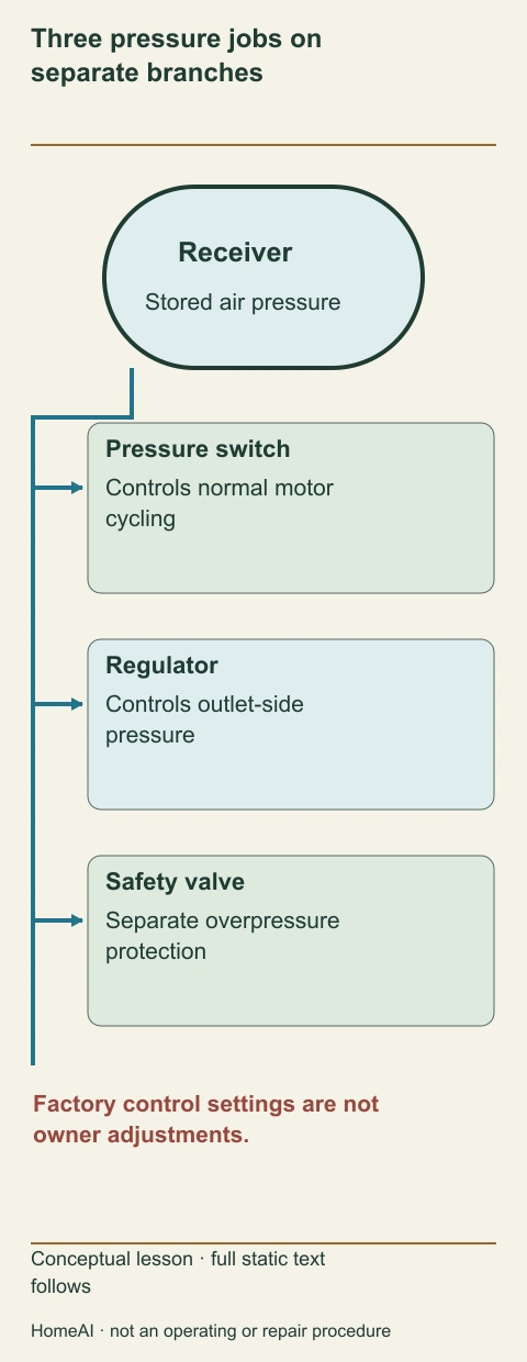
- Pressure switch
Starts/stops the motor at factory conditions.
- Regulator
Controls outlet-side pressure.
- Safety valve
Protects against excessive receiver pressure.
- On/off switch
Enables automatic operation in the named example.
What does this illustration leave out?
Named Bostitch function example; no setpoint, adjustment, test or replacement design. This illustration explains an idea. It is not an installation guide.
Which control or protective function does the actual service report address?
Explore this with HomeAI ↗Opens an editable question. Nothing is sent until you choose to send it.Three pressure jobs on separate branches
The pressure switch manages normal tank cycling, the regulator controls outlet pressure, and the safety valve is separate excessive-pressure protection. Turning one outlet knob does not redefine all three jobs.
- Pressure switch
- Starts/stops the motor at factory conditions.
- Regulator
- Controls outlet-side pressure.
- Safety valve
- Protects against excessive receiver pressure.
- On/off switch
- Enables automatic operation in the named example.
Figure scope: Named Bostitch function example; no setpoint, adjustment, test or replacement design.
A useful question: Which control or protective function does the actual service report address?
Full wording shown in this figure
- Three pressure jobs on
- separate branches
- Receiver
- Stored air pressure
- Pressure switch
- Controls normal motor
- cycling
- Regulator
- Controls outlet-side
- pressure
- Safety valve
- Separate overpressure
- protection
- Factory control settings are not
- owner adjustments.
- Conceptual lesson · full static text
- follows
- HomeAI · not an operating or repair procedure
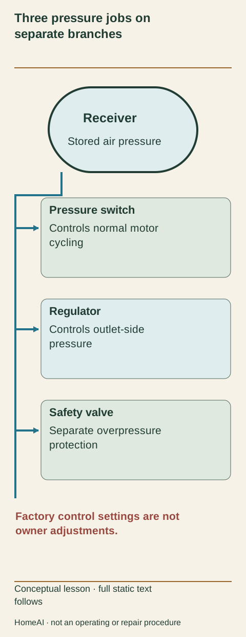
Three different pressure jobs
- Pressure switchJob: Controls normal motor cycling from tank pressureBoundary: Factory settings are not owner adjustments
- RegulatorJob: Controls outlet-side pressureBoundary: Does not redefine receiver limits
- Safety valveJob: Protects against excessive tank pressureBoundary: Not the normal cycling control
Named BostitchSeptember2019 arrangement; other products differ.
Why are there two gauges, and what does each leave out?
The tank gauge reports pressure at the receiver-related point. The outlet gauge reports pressure on the regulated side. In the named manual, outlet pressure is less than or equal to tank pressure. The two readings describe different parts of the system; they are not duplicate instruments that should always show the same number, and neither is a direct display of the air quantity delivered during a work interval.
A static outlet indication and conditions while an accessory uses air can differ. The manual acknowledges that some drop during use is normal and discusses excessive drop separately. This does not give HomeAI a universal acceptable-drop value. The service question is what occurred under identified conditions and whether the actual compressor, route and accessory requirements were met.
Keep units and instrument identity with any recorded reading. PSI or PSIG describes a pressure condition; CFM or SCFM describes air delivery per time under specified reference conditions. A gauge face cannot establish a pump's flow rating, and a tank-volume label cannot establish a compatible tool pressure. Do not convert one attractive catalogue number into all three quantities.
Record readings only when already safely available in ordinary authorized use; do not run a faulty machine or attach a gauge to create a comparison. An unreadable, damaged or suspect gauge belongs in the service discussion. The picture's dial marks are conceptual and carry no operating recommendation. Use the actual product and accessory instructions for the permitted conditions, with professional help where those requirements are uncertain.
Pressure at two places is not air delivery
Tank and outlet gauges describe pressure at different points. Air delivery is a different quantity per time, and receiver volume is a different storage quantity.
Numbers identify the parts explained below.
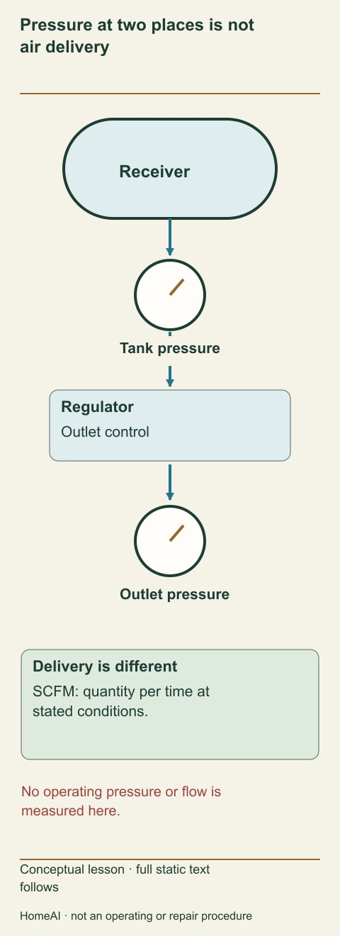
- Tank pressure
A pressure condition at the receiver.
- Outlet pressure
A regulated-side pressure condition.
- SCFM delivery
Air quantity per time under stated reference/pressure conditions.
- Tank volume
Receiver size, not continuing pump delivery.
What does this illustration leave out?
No operating readings, flow curve or acceptable pressure drop is assigned. Units are vocabulary, not measurements. This illustration explains an idea. It is not an installation guide.
Does the record distinguish tank pressure, outlet conditions and published delivery?
Explore this with HomeAI ↗Opens an editable question. Nothing is sent until you choose to send it.Pressure at two places is not air delivery
Tank and outlet gauges describe pressure at different points. Air delivery is a different quantity per time, and receiver volume is a different storage quantity.
- Tank pressure
- A pressure condition at the receiver.
- Outlet pressure
- A regulated-side pressure condition.
- SCFM delivery
- Air quantity per time under stated reference/pressure conditions.
- Tank volume
- Receiver size, not continuing pump delivery.
Figure scope: No operating readings, flow curve or acceptable pressure drop is assigned. Units are vocabulary, not measurements.
A useful question: Does the record distinguish tank pressure, outlet conditions and published delivery?
Full wording shown in this figure
- Pressure at two places is not
- air delivery
- Receiver
- Tank pressure
- Regulator
- Outlet control
- Outlet pressure
- Delivery is different
- SCFM: quantity per time at
- stated conditions.
- No operating pressure or flow is
- measured here.
- Conceptual lesson · full static text
- follows
- HomeAI · not an operating or repair procedure
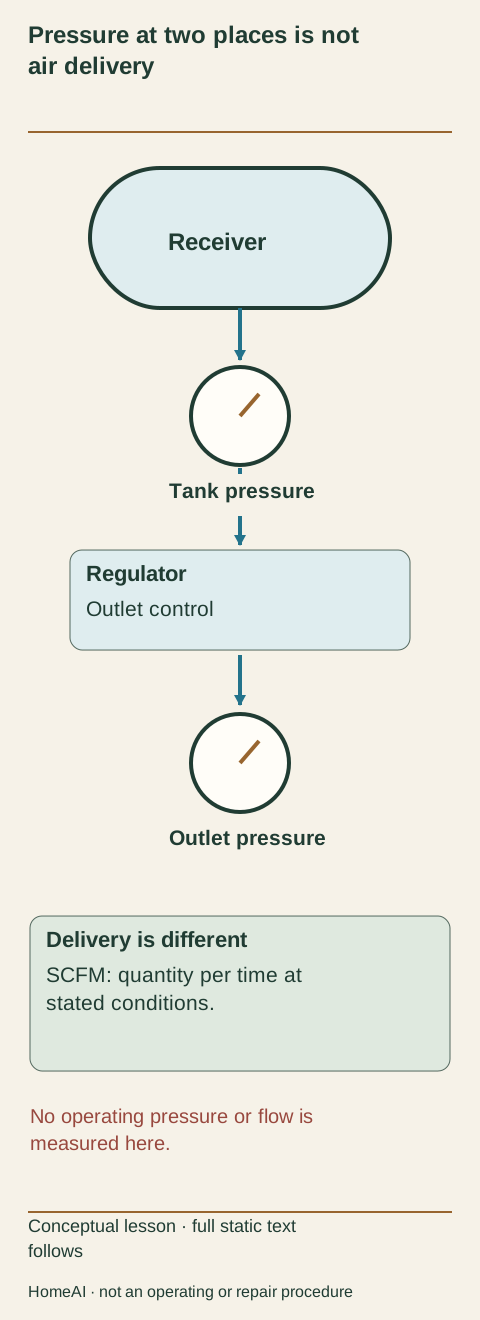
How should air delivery and tool demand be compared?
An accessory requires an appropriate pressure and an adequate air supply during its intended use. Both matter. A high maximum tank pressure does not guarantee enough continuing flow for an air-hungry tool. Conversely, a large advertised flow at a different pressure or under a different reference condition is not automatically the relevant value for the proposed task.
The named Bostitch manual illustrates this distinction with SCFM ratings at separately stated pressures and a separate receiver capacity. This guide does not turn those dated model numbers into a tool recommendation. Obtain the actual accessory's required pressure, delivery information and usage conditions, then compare them with the actual compressor's specification. Keep ratings in their original units and named test conditions.
Work pattern matters as well. A short intermittent demand and a continuous demand can draw differently on the receiver and pump. Manufacturer duty-cycle instructions describe how the equipment may be used; they are not erased because an accessory continues to move. Bostitch's named manual discusses an average duty cycle for its model. That recommendation is not a universal number for every oil-free or household compressor.
The native comparison deliberately uses a qualitative reserve-versus-continuing-demand diagram rather than invented performance curves. It explains why a tool may work briefly and then struggle without proving the pump is defective. A useful supplier or service assessment states the intended task and supported combination. Do not use maximum tank pressure or motor power as a substitute for the missing air-delivery information.
A brief reserve and continuing demand differ
A receiver can supply an initial reserve while a pump has its own continuing delivery. An accessory working briefly does not establish that the combination supports prolonged demand.
Numbers identify the parts explained below.
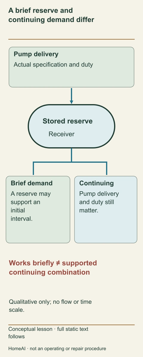
- Stored reserve
Can support a limited initial interval.
- Pump delivery
Remains bounded by the actual specification.
- Accessory demand
Depends on the intended task and use pattern.
- Duty requirements
Remain product-specific even when the tool still moves.
What does this illustration leave out?
Qualitative relationship only; no invented flow, duty interval, capacity or performance curve. This illustration explains an idea. It is not an installation guide.
Are accessory demand and compressor delivery compared at the same relevant conditions?
Explore this with HomeAI ↗Opens an editable question. Nothing is sent until you choose to send it.A brief reserve and continuing demand differ
A receiver can supply an initial reserve while a pump has its own continuing delivery. An accessory working briefly does not establish that the combination supports prolonged demand.
- Stored reserve
- Can support a limited initial interval.
- Pump delivery
- Remains bounded by the actual specification.
- Accessory demand
- Depends on the intended task and use pattern.
- Duty requirements
- Remain product-specific even when the tool still moves.
Figure scope: Qualitative relationship only; no invented flow, duty interval, capacity or performance curve.
A useful question: Are accessory demand and compressor delivery compared at the same relevant conditions?
Full wording shown in this figure
- A brief reserve and
- continuing demand differ
- Pump delivery
- Actual specification and duty
- Stored reserve
- Receiver
- Brief demand
- A reserve may
- support an
- initial
- interval.
- Continuing
- Pump delivery
- and duty still
- matter.
- Works briefly ≠ supported
- continuing combination
- Qualitative only; no flow or time
- scale.
- Conceptual lesson · full static text
- follows
- HomeAI · not an operating or repair procedure
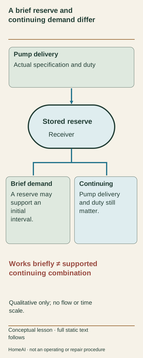
A reserve is not continuing delivery
- Tank volumeUseful meaning: Size of the air receiverRemaining question: What can the pump deliver during continued work?
- Tank pressureUseful meaning: A pressure condition in the receiverRemaining question: What reaches the accessory during demand?
- Air deliveryUseful meaning: Quantity per time at stated conditionsRemaining question: Does it match the accessory and duty pattern?
Conceptual comparison; no invented performance curve or tool recommendation.
Why does water collect in a machine that takes in air?
The surrounding air contains moisture. The named Bostitch manual explains that compressed-air systems generate condensate that can collect at drain points, including tanks and treatment equipment. In a receiver, that collected water is different from the useful stored-air reserve. An oil-free pump designation does not mean the entire air stream is dry, clean or suitable for every sensitive use.
The manual warns that retained water can corrode and weaken the tank. It also notes that condensate can contain oil or other substances and may have disposal requirements. A brown discharge or visible external rust is an observation, not a measurement of the remaining wall or a complete cause diagnosis. Conversely, an attractive outer paint finish cannot establish a sound inside surface.
The conceptual receiver close-up shows a shallow collected-water region and an illustrative inner-wall relationship. No crack or wall-thickness assessment is supplied. It explains why the matching maintenance and retirement instructions matter. It does not tell the owner to open a valve, dismantle a blocked drain, collect pressurized discharge or carry out a corrosion test. Obtain the correct procedure and appropriate service help for the actual unit.
Keep maintenance history factual: which task was performed, by whom, under which instructions, and what concern was found. Do not infer a tank's remaining life from age alone or rewrite unknown drainage history as neglect. If there is a tank leak, damage or other pressure-vessel concern, stop use and seek manufacturer or qualified service direction; do not weld, seal or re-pressurize it to evaluate a repair.
Stored air and collected water differ
The receiver stores compressed air while condensate can collect at its low point. The named manual connects retained water with corrosion concerns and model-specific care.
Numbers identify the parts explained below.
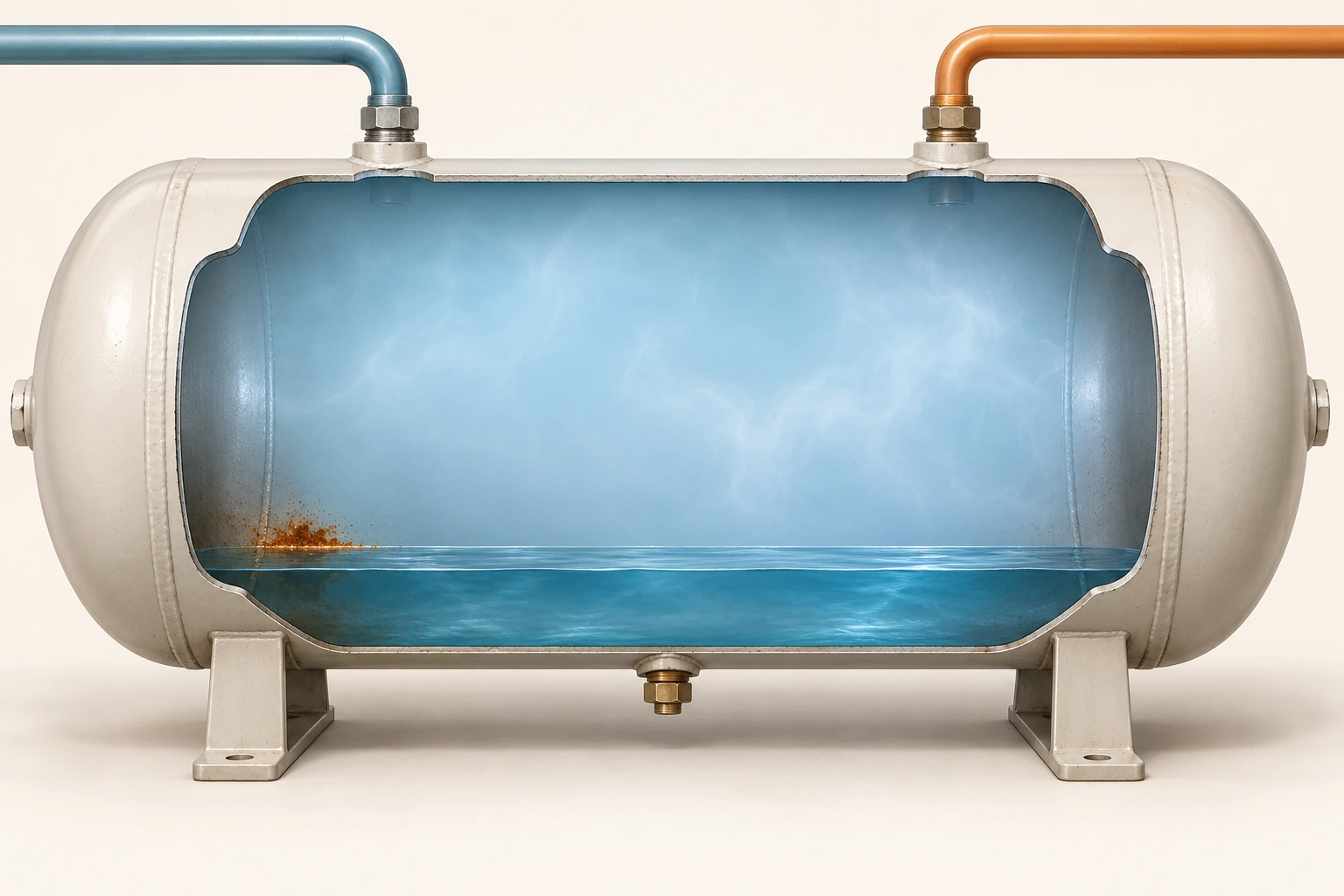
- Air region
Stores compressed-air energy.
- Collected water
Condensate is different from the useful air reserve.
- Tank wall
Pressure-containing condition needs appropriate assessment.
- Closed fitting
Does not show pressure release or maintenance being performed.
What does this illustration leave out?
Conceptual air and condensate regions with illustrative staining; no normal water amount, active drain operation, corrosion measurement, wall thickness or remaining life is established. This illustration explains an idea. It is not an installation guide.
Which actual maintenance, warning-label and tank-condition questions remain?
Explore this with HomeAI ↗Opens an editable question. Nothing is sent until you choose to send it.What do oil-free, filtration and dry-air claims really mean?
Oil-free describes a pump arrangement; it is not a declaration that all air reaching an accessory is contaminant-free. The named Bostitch manual warns that its compressed air can contain moisture and oil mist and that some accessories require filtered air. The source air, stored condensate and downstream route all matter to the intended use. A clean-looking hose cannot answer those questions by itself.
Different tasks can require different air treatment. The appropriate accessory manufacturer and system professional determine the actual filtration, drying or lubrication requirements. Adding an unidentified filter does not make the supply breathing air or approve a paint, food or medical application. This guide supplies no respiratory-air design, spray-finishing recipe or contaminant-removal percentage.
Keep lubrication questions separated too. An accessory may have instructions that differ from those for the compressor pump. Do not add oil to an oil-free pump or into a hose because a different tool's manual mentions lubrication. The actual equipment identities and compatibility instructions need to travel together. A previous owner's bottle or accessory set is not evidence of the correct product or method.
For a surface-quality complaint, describe the actual result and intended material rather than declare water or oil contamination from a photograph. Equipment condition, receiving material and application method can contribute different explanations. The compressor provider and application specialist may need separate scopes. The useful decision is to resolve the required air quality and supported system before buying a filter that merely fits the connector.
How do hoses, couplers and accessories become part of the system?
A hose carries air from the regulated outlet to the accessory. Couplers join compatible components; their physical fit is only one part of suitability. Pressure ratings, condition and manufacturer compatibility matter throughout the route. Bostitch warns against worn accessories and excessive pressure, and identifies hose whip as a hazard during connection or disconnection. Stored energy must be managed under the actual complete instructions.
Do not pull apart a connected fitting, tighten a pressurized leak or use a hand to locate escaping air. Do not repair a damaged hose with tape or fit an improvised adaptor to make an unsuitable tool work. A supplier can identify the intended connection system; a service provider can assess faults within the appropriate scope. This guide gives no connection, disconnection or depressurization sequence.
An air route can also affect the conditions reaching an accessory. The named troubleshooting section includes a damaged hose, leaks, restrictions and inadequate delivery among different possibilities for poor performance. A full tank reading therefore does not rule out a downstream issue. The appropriate assessment identifies the whole route rather than assigning the symptom to the most expensive part at its beginning.
The context picture keeps the unplugged electrical lead separate from a hose connected to an accessory. Unplugging removes electrical supply but does not establish an empty receiver or hose. The illustration supplies no permission to operate that tool, no pressure setting and no approved workshop layout. Ask what the accessory actually needs, which components are matched, and which conditions were assessed. The meaningful lesson is a complete supported route, not a collection of fittings that can be screwed together.
What matters about the compressor's location and electrical supply?
The motor and pump generate heat and need their intended cooling airflow. The named manual requires a clean, dry, ventilated location and warns that blocked openings can cause overheating. A cloth thrown over the shroud to reduce noise changes that relationship. Keep materials and obstacles away according to the actual model's instructions; this guide does not supply a universal clearance or sound enclosure.
Electrical contacts can produce sparks, so flammable vapours and combustible surroundings are a separate concern. Do not treat the compressor as suitable beside fuel, solvents or a spraying task because it has no combustion engine. An application involving hazardous materials needs its own professionally resolved controls. No conceptual workshop picture can establish ventilation, exposure control or fire-safety approval.
The named electric compressor requires a suitable electrical supply and warns against wet operation, damaged cords and unqualified repairs. A physically fitting outlet is not proof of the required grounding, circuit capacity or protection. Repeated interruption belongs with a qualified electrician and equipment service provider; do not increase breaker or fuse ratings, alter plugs or keep resetting a circuit to complete the job.
Place and handle the actual equipment under its instructions. Bostitch warns about falling from elevated surfaces and says to use a stable position. A workbench may be convenient for reading a gauge but unsuitable for operating that portable unit. The owner's preparation should identify the actual site, electrical supply, air route and task before starting, including an alternative if those requirements cannot be met.
The machine and accessory need a supported route
The unplugged electrical lead and connected air hose are separate routes. Removing electrical input does not establish that the receiver, hose or accessory contains no stored pressure; the intended combination still needs compatible parts and adequate delivery.
Numbers identify the parts explained below.
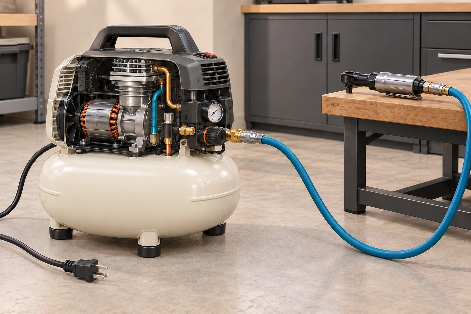
- Electrical lead
A different route from compressed air.
- Cutaway shroud
Illustration-only anatomy; real protective covers stay in place.
- Air hose
Carries stored energy under appropriate instructions.
- Accessory
Has its own compatibility and demand requirements.
What does this illustration leave out?
Conceptual cutaway, not operation with a removed cover. No actual pressure, approved workshop, circuit, tool use or completed isolation is shown. This illustration explains an idea. It is not an installation guide.
Which supply, route, accessory and site requirements were actually resolved?
Explore this with HomeAI ↗Opens an editable question. Nothing is sent until you choose to send it.Which observations are useful without an owner pressure test?
Start with the identity, matching manual, accessory requirements and an account of ordinary use. Preserve whether the pump started, whether the motor later stopped, which gauge was read, and when the accessory changed behaviour. Keep those observations separate. Compressor slow is less useful than the accessory worked briefly, then slowed while the tank indication fell during the previously attempted task.
Do not recreate a leak, block an outlet, hold the motor running or deliberately operate a safety valve to obtain evidence for HomeAI. A quiet machine is not necessarily isolated, and stored pressure remains a hazard after power removal. Keep maintenance and pressure release with the actual instructions and appropriate competence. An observation plan should never require entry into a hazard it is supposed to explain.
If unusual noise, vibration, excessive pressure, a tank leak or damaged electrical parts are reported, stop use and obtain suitable service direction. Do not put an ear close to a fitting or use skin to feel for air. Record an already-noticed sound as a report, not as a confirmed leak location. The technician can choose appropriate methods and interpret the results under a defined scope.
Photographs of externally accessible labels and assembled equipment may help identify parts without removing a shroud or reaching beneath the tank. Their limits remain straightforward: they do not measure wall thickness, verify a relief device or establish output performance. A better service request combines those ordinary records with the original complaint and asks a specific question, rather than ask the owner to certify equipment before seeking help.
Why might a tool slow down while the compressor runs?
Several mechanisms can produce a similar experience. The accessory may use air faster than the compressor can supply under its intended work pattern. The route may have a leak, damaged hose or restriction. The regulator or another compressor component may need assessment, or the accessory itself may be faulty. A running motor does not distinguish these possibilities, and a maximum-pressure sticker does not rule out a delivery mismatch.
The named Bostitch troubleshooting section separately lists excessive use, insufficient compressor capacity for the accessory, hose damage, a restricted check valve and leaks. This guide adopts the alternatives as questions, not its repair instructions. Do not tighten fittings, remove valves, open an electrical terminal box or increase a setting because one line of a general guide resembles the reported symptom.
A motor that fails to run raises another set of possibilities, including electrical supply and overload protection or equipment faults. A thermal stop is not proof that cooling alone was the cause; demanding use, site conditions and a fault can require different assessments. Preserve the timing and the actual indicators or switch state without repeated reset trials. Qualified people can separate electrical supply from compressor service.
Ask for a report that identifies which route and operating conditions were assessed. A limited no-load run does not establish compatibility with a continuous-demand tool. Conversely, an inadequate tool combination does not establish that the pump needs replacement. The decision should follow the assessed mechanism: resolve the supported application, repair an identified fault appropriately, or select different equipment when the intended task exceeds its documented scope.
What should a service report and equipment handover contain?
Identify the compressor by its full model, type and serial or date information and retain the actual tank warning label details. A service report should state the complaint, findings, work, relevant component identities and remaining limitations. If a control or delivery question was assessed, ask under what conditions. An invoice saying serviced is useful history but does not describe every safety or performance result.
A trained equipment technician can assess the pump, regulator, controls and machine within their competence. An electrician addresses the actual electrical supply and wiring. A pressure-vessel concern needs appropriate manufacturer or qualified specialist direction rather than household patching. The provider's actual scope matters more than a reassuring trade label, and this guide invents no certification, availability or inspection result.
Keep maintenance and retirement requirements with the exact product. The named manual includes tasks for collected water and a tank warning label, but its dated procedure is not a universal household service interval. A used compressor without legible identity or supported maintenance information raises an unresolved decision. Low purchase price and a successful momentary demonstration cannot replace that information.
For disposal, collected liquids and accessories, ask the appropriate current local receiving service and manufacturer. Do not discharge condensate into a drain or abandon a pressurized vessel on the strength of a generic internet instruction. This guide claims no municipal acceptance rule. The handover is complete enough to be useful when the next owner can identify both the intended work and the matters still requiring action.
Work through a fictional compressor and air-sander mismatch
Fictional owner Evan inherits a compact receiver compressor and buys an air sander. The sander moves well briefly, then slows while the compressor runs for a long period. The old sales note highlights maximum tank pressure, but the sander's continuing air requirement was never compared with delivery at its required conditions. Evan has no evidence of a tank leak or pump fault and does not stage another prolonged trial.
He gathers the actual manuals and asks the supplier to compare the proposed combination. The fictional written comparison finds that the sander's stated continuing demand exceeds the compressor's published delivery at the relevant stated pressure. The units and rating conditions are retained in the real comparison record; this educational example supplies no invented numerical product rating. The finding explains why a reserve could help briefly without supporting the continued task.
An equipment service report separately records the condition and limited checks it actually covered. It does not declare the old receiver to have unlimited life or approve every accessory. Evan retains a hose-condition concern identified in that report as a separate task rather than claiming the demand mismatch explains everything. No household air-release, valve test or electrical measurement is performed for the example.
His concrete decision is to defer the unsuitable sander combination and obtain a supported alternative for that task, while resolving the identified machine and hose requirements before other use. Buying a larger receiver alone would not answer the continuing-delivery question. The fictional result teaches a decision pathway, not a product recommendation, tank certification or permission to resume operating a real compressor.
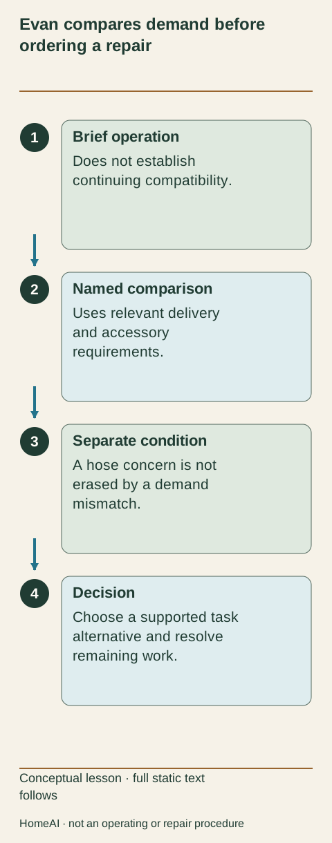
Evan compares demand before ordering a repair
The fictional comparison identifies an unsupported continuing demand. Evan retains the separate hose concern and defers that tool combination instead of assuming that a larger tank fixes everything.
Numbers identify the parts explained below.
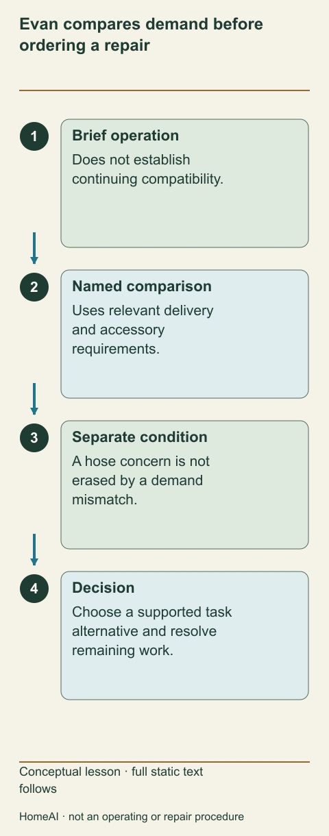
- Brief operation
Does not establish continuing compatibility.
- Named comparison
Uses relevant delivery and accessory requirements.
- Separate condition
A hose concern is not erased by a demand mismatch.
- Decision
Choose a supported task alternative and resolve remaining work.
What does this illustration leave out?
Fictional records; no actual rating, pressure test, service approval or product recommendation. This illustration explains an idea. It is not an installation guide.
Which conclusion follows from the documented comparison, and which equipment concern remains separate?
Explore this with HomeAI ↗Opens an editable question. Nothing is sent until you choose to send it.Evan compares demand before ordering a repair
The fictional comparison identifies an unsupported continuing demand. Evan retains the separate hose concern and defers that tool combination instead of assuming that a larger tank fixes everything.
- Brief operation
- Does not establish continuing compatibility.
- Named comparison
- Uses relevant delivery and accessory requirements.
- Separate condition
- A hose concern is not erased by a demand mismatch.
- Decision
- Choose a supported task alternative and resolve remaining work.
Figure scope: Fictional records; no actual rating, pressure test, service approval or product recommendation.
A useful question: Which conclusion follows from the documented comparison, and which equipment concern remains separate?
Full wording shown in this figure
- Evan compares demand before
- ordering a repair
- 1
- Brief operation
- Does not establish
- continuing compatibility.
- 2
- Named comparison
- Uses relevant delivery
- and accessory
- requirements.
- 3
- Separate condition
- A hose concern is not
- erased by a demand
- mismatch.
- 4
- Decision
- Choose a supported task
- alternative and resolve
- remaining work.
- Conceptual lesson · full static text
- follows
- HomeAI · not an operating or repair procedure
How do Canadian and product limits change the answer?
CCOHS provides Canadian occupational education about compressed-air hazards and explicitly notes jurisdiction-dependent cleaning restrictions. This guide does not turn that workplace map into universal household law or offer a supposedly safe cleaning-pressure number. The practical owner boundary is clear: do not direct compressed air at people or use it on skin or clothing, and do not adopt a cleaning application without an appropriately resolved safe method.
The Bostitch September2019 manual is a named product source, not current proof of market availability, a household installation approval or a Canadian warranty entitlement. Quincy's undated current glossary explains a general piston mechanism. Neither source determines the condition of an inherited compressor. Keep the source edition, actual product and assessed question together when using their explanations.
An oil-free label, small tank or familiar brand does not remove electrical, pressure, heat, noise or accessory hazards. Those are separate relationships to understand and manage under the actual instructions. A useful household plan also considers other people, pets and the intended work area. It does not assume that equipment suitable for one brief task is suitable for another more continuous or contamination-sensitive application.
The next useful question is often narrow: what does this accessory require, what can this compressor deliver under those conditions, and which route or condition still needs professional assessment? Clear answers can prevent an unsupported repair order or unsuitable purchase. They do not amount to blanket approval of a workshop, pressure vessel or every use of a hose connected to compressed air.
Keep learning about the connected parts
- Pressure washers: follow the supply, pump, controls and cleaning target
- Why does a breaker trip? Understand GFCI and AFCI protection
- Portable lithium-ion batteries: connect charging, storage and response
- Build a home-care record that the next person can understand
Canadian context and authorities · Visual atlas · Learning labs
Practice the distinction.
Evan’s briefly effective air sander
Fictional learning example:a compact compressor supplies an air sander briefly, then the tool slows during prolonged use.
Reported observations
- The old note highlights maximum tank pressure, not delivery at the accessory’s required conditions.
- A fictional supplier comparison later identifies continuing demand greater than the relevant published delivery.
- A separate service report retains a hose-condition concern; no tank certification or owner pressure test is supplied.
Compare the explanations
Expand each possibility to see the evidence needed to distinguish it. Similar symptoms can have different mechanisms.
A reserve masks a continuing-delivery mismatch
Stored air can support a brief interval without making the pump adequate for the continuing task.
Matched compressor/accessory specifications, units and stated work conditions.
The equipment or route has another unresolved condition
A demand mismatch does not erase a separate identified hose or machine concern.
Actual bounded equipment/route assessment and recorded findings.
A useful next question
Evan defers the unsupported sander combination, obtains a supported task alternative, and resolves the identified machine and hose requirements before other use.
Fictional comparison; no real product recommendation, pressure test, tank life finding or permission to resume use.
Know what the words mean.
- Receiver
- The pressure-containing tank that stores compressed air between pumping and outlet demand.
- Reciprocating pump
- A pump in which a piston repeatedly moves within a cylinder to compress air.
- Tank check valve
- The named example’s one-way tank-inlet function that helps retain pressure after pumping stops.
- Cut-in
- The factory pressure condition at which the named pressure switch restarts the motor.
- Cut-out
- The factory pressure condition at which the named pressure switch stops the motor.
- Regulator
- A control for outlet-side pressure, distinct from the receiver’s automatic pumping limits.
- Safety valve
- A protective pressure-relief device, not the normal outlet regulator or an owner adjustment.
- SCFM
- Standard cubic feet per minute, a delivery quantity whose reference and pressure conditions matter.
- Condensate
- Collected liquid associated with moisture in a compressed-air system; its composition and disposal need actual context.
- Duty cycle
- The manufacturer’s permitted or recommended operating pattern under stated conditions, not a universal continuous-use promise.
Questions to bring
to the conversation.
- Which exact compressor, tank identity, manual and accessory requirements are retained?
- What conditions do delivery and pressure specifications actually describe?
- Which reported event suggests a route, demand, control or equipment assessment?
- What maintenance, retirement, electrical and accessory tasks remain unresolved?
Separate a showing observation, an existing record and a new professional assessment. Unknown means a question remains; it does not automatically mean a defect.
Use the evidence planner ↗Go to the source.
Original HomeAI explanation informed by these public references. Sources support the underlying guidance; they have not reviewed or endorsed HomeAI. Diagrams are conceptual, and calculator outputs depend on your inputs.
Read October20, 2026 in America/Edmonton. Named BostitchSeptember2019 North American manual, complete English physical1–3, and Quincy’s current undated complete piston entry supply mechanisms. CCOHSOctober2022 compressed-air education has workplace/jurisdiction limits; no household legal map or safe cleaning pressure adopted. No tank life, pressure test, repair, electrical approval or accessory permission; worked household fictional.
Publication & source review
First published .
Sources reviewed .
Have a question about your home?
Start with the symptom, timing and what you have observed.
Ask HomeAI